

| Categories | Alinco Brand Manuals, Alinco DJ Manuals, Alinco Manuals, Communications Manuals, Two-Way Radio Manuals |
|---|---|
| Document Type | Transceiver and Communications Radio Operator's Guide. VHF radio Instruction Manual in PDF. |
| Tags | Alinco DG-X10 |
| Download File |
|
| Document File Type | |
| Publisher | alinco.com |
| Wikipedia's Page | Alinco |
| Copyright | Attribution Non-commercial |
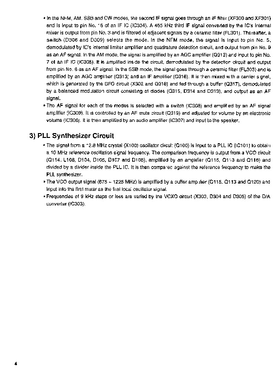
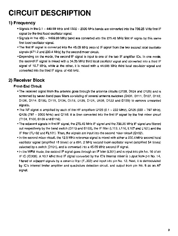
CONTENTS SPECIFICATIONS ··2 · CIRCUIT DESCRIPTION 3 .SEMICONDUCTOR DATA ··7 · EXPLODED VIEW · PARTS LIST· · ADJUSTMENT· · PC BOARD VIEW BLOCK DIAGRAM .· ·31 · CIRCUIT DIAGRAM· ·33 II;bI ALINCO, INC. · In the NFM, AM, SSB and CW modes, the second IF signal goes through an IF filter (XF300 and XF301) and is input to pin No. 16 of an IF IC (IC304). A 455 kHz third IF signal converted by the IC’s internal mixer is output from pin NO.3 and is filtered of adjacent signals by a ceramic filter (FL301).
Transceiver Radio Manual Free Download. Radio Communications Operator’s Guide. Free VHF radio Instruction and Manual Download PDF.
Thereafter, a switch (0306 and 0309) selects the mode. In the NFM mode, the signal is input to pin No.5, demodulated by IC’s intemallimiter amplifier and quadrature detection circuit, and output from pin No.9 as an AF signal. In the AM mode, the signal is amplified by an AGC amplifier (0313) and input to pin No. 7 of an IF IC (IC305). It is amplified inside the circuit, demodulated by the detection circuit and output from pin NO.8 as an AF signal. In the SSB mode, the signal goes through a ceramic filter (FL303) and is amplified by an AGC amplifier (0313) and an IF amplifier (0316). It is then mixed with a carrier signal, which is generated by the BFO circuit (X302 and 0318) and fed through a buffer (0317), demodulated by a balanced modulation circuit consisting of diodes (0315, 0314 and 0313), and output as an AF signal. · The AF signal for each of the modes is selected with a switch (IC308) and amplified by an AF signal amplifier (IC309). It is controlled by an AF mute circuit (0319) and adjusted for volume by an electronic volume (IC306). It is then amplified by an audio amplifier (IC307) and input to the speaker. 3) PLL Synthesizer Circuit · The signal from a 12.8 MHz crystal (X100) oscillator circuit (0100) is input to a PLL IC (IC1 01) to obtain a 10 MHz reference oscillation signal frequency. The comparison frequency is output from a VCO circuit (0114, L108, 0104, 0105, 0107 and 0108), amplified ….. …